DESIGN
FEATURES OF THE ADDIS ABABA RING ROAD PROJECT
Consultant:
- Parkman Limited.
1.
Introduction
The Addis Ababa Ring road was
initiated as part of the city's commitment towards implementing the city
master plan and enhancing peripheral development.
With this objective and the
principle of efficient utilization of resources and time and also with
the need to create construction ease, the Ring Road was divided into
three major phases. These phases connect all the five main gates in and
out of Addis with all other Regions (Jimma, Debre Zeit, Asmara, Gojjam
and Ambo)
When the ring Road is completed, it
is expected that heavy vehicles entering the city of Addis Ababa from
the five main radial routes will be diverted into the ring road either
to bypass Addis Ababa completely or to transfer to another radial route
to suite their eventual destination and in doing so avoid the city
center. There will also be transfer of traffic to the Ring Road from the
traffic that currently uses a network of roads within the city.
2.
Traffic
The task of traffic study is
concerned with the development of future traffic and axle-load forecasts
in order to provide suitable data to assist with the design work. For
this propose, a diversion curve analysis has been utilized to assess the
potential diversion of existing radial traffic to the Ring Road, if it
were open today. Growth factors have then been applied to this diverted
traffic to produce estimates of forecast traffic flows. A forecast year
of 2020 has been adopted, 20 years after the proposed completion of Ring
Road in the year 2000. In addition, consideration has also been given to
the impact of major development proposals adjacent to the Ring Road
line. Such development is likely to contribute significantly to the
levels of traffic on the Road.
Traffic surveys have been carried
out to provide up-to-date data of the flow of vehicles on the five main
radial routes that the proposed Ring Road will intercept. In addition,
surveys have also been undertaken on those sections of existing road
that lie on the line of the proposed Ring road and those that will form
part of the Ring Road. Sample turning movement count surveys have been
undertaken at two key existing junctions, and a sample origin
destination survey (O/D Survey) of’ heavy goods vehicles was carried
out at the same time and location as the axle-load survey. Table 1
presents the result of design years traffic forecasts
For the maximum flow of’ 30500 24
hr ADT, AASHTO Highway capacity manual recommends 4-lane divided urban
arterial road with some at-grade junctions. In addition to the 4 lane
divided carriageway, a 6.6 m frontage road will be provided on each
side. The maximum flow of the frontage roads is expected to he of the
order of 23500 24 hour ADT, or about 12000 ADT on each frontage road.
Table
I Design Year (2020) Traffic Forecasts
|
|
Ring Road Section
|
2020 tow-way 24 Hr ADT flow
|
|
Main
Route
|
Frontage
Roads
|
Total
Flow
|
|
Ambo Rd to Jimma Rd
|
14,700
|
11,300
|
26,000
|
|
Jimma Rd to Debre Zeit Rd
|
22,000
|
|
22,000
|
|
Debre Zeit Rd to Bole Rd
|
24,000
|
|
24,000
|
|
Bole Rd to Asmara Rd
|
30,500
|
23,500
|
54,000
|
3.
Road Cross Sections and Other Features
The basic design philosophy for the
Ring road Project was to ensure ease of movement for through traffic. To
achieve this, there was need to segregate through traffic from local
traffic. This has been achieved by providing a dual two-lane carriageway
for the main roads and two separate two-lane frontage roads for local
traffic.
The proposed typical cross section
consists of the following elements and is shown schematically in Figure.
1
Sidewalk
3.0m
Frontage Road
6.6m
Separator
1.7m
Mainline
7.2m
Median
3.0m
Mainline
7.2m
Separator
l.7m
Frontage Road
6.6m
Sidewalk
3.0m
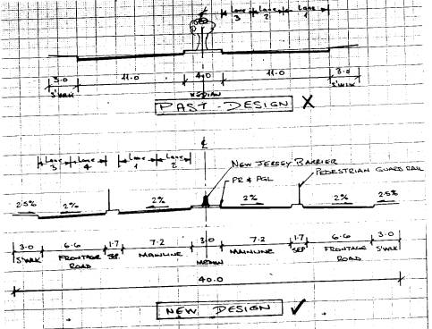
Fig. 1. Schematic diagram of road
cross - section geometry
3.1
Junction Design
Five major junctions were originally
identified along the ring road at the five radial routes from Addis
Ababa, namely:
Ambo Road
Jimma Road
Debre Zeit Road
Bole Road
Asmara Road
In
order to cater for the projected traffic defined in the Traffic Study
and deal with the predicted turning movements at these junctions at
grade roundabouts were envisaged originally. Where the turning movement
within the tight junction became excessive, consideration was given to
grade separation of the junction. Therefore grade-separated flyovers
will be provided at Bole and at Old Airport to take the 4 lanes divided
carriageway of the main through route over the ground level. Grade -
separation is also provided at the junction between the Ring Road and
Deberzeit Road, at Kality. Because of’ the topography at this location
and the proposed vertical profile of the alignment, the Ring Road will
pass under the roundabout junction of the Debreziet Road.
The location of these five major
junctions resulted in the road being divided into segments of 4 to 11 km
lengths. As a means of limiting these excessive journey times,
intermediate junctions in the form of roundabout are proposed at
specific locations. These junctions will provide additional turning
facilities and where appropriate, give access to development areas
already indicated in Addis Ababa’s Master Plan.
In order to accommodate the dual
two-lane mainline and the two - lane frontage roads on either side, it
is proposed to merge the section into a dual three - lane carriageway
prior to any roundabout junction. These dual three - lane will then be
carried through the roundabout before diverging back to original dual
two-lane cross-section.
3.2
Pedestrian Facilities
Roughly 70 percent of all
inhabitants of Addis Ababa travel by foot and the provision for
pedestrian movement is an important aspect of the Ring Road Design.
Pedestrian facilities will be
provided at each junction by way of delineated footpath crossings. In
addition footbridges will be provided at numerous locations along the
length of the road.
3.3
Side Roads
In the design of the Ring road, all
side road access is restricted to the two - lane frontage roads. To
allow side roads direct access to and from the main line, will multiply
the potential points of conflict between all forms of transport i.e.
whether by vehicle, pedestrian or animal. The roads, operating in one
direction only, would merge and diverge from the mainline ‘at grade’
roundabout junction in accordance with AASHTO’s guidelines on lane
balance.
The two-lane frontage road will be
reduced to a single lane and merged with the two lane mainline to form a
three lane approach to the junction. As the road leaves the junction the
process is reversed with the three-lane road diverging into two lanes
and one single lane. Once the separator is formed the single lane will
be then widened to form the two lane and the frontage lane, this
procedure will also be used where the road alignment approaches any
bridge structure, which will be designed to carry a dual three -lane
road.
4.
Materials and Pavement
4.1
Existing Ground Condition
Analysis of test pit investigations
indicates that black cotton soil is the predominant soil type. The black
cotton soil generally exhibits very high swell values and is therefore
classified as unsuitable material as fill.
4.2
Pavement Design
4.2.1
Axle Load
An axle- load survey was conducted, and
based on the traffic forecast result, the equivalent standard Axle was
calculated on a year basis. The Table 3 indicates the cumulative ESAs
for one direction and for different design life periods for three road
sections.
In Highway capacity terms the Ring
Road has been designed as a dual two-lane road, Principal Arterial Road
(AASHTO definition). A lane distribution factor should be taken into
account which allows for the distribution of the heavy vehicle traffic
into the slow (inner) and the fast (outer) lanes.
For a principal arterial road AASHTO
recommends as a guide, a distribution between 80% to 100% of heavy
vehicles using the slow lane. Therefore a median of 90% of the traffic
was taken for design of the inner lane (slow lane).
The pavement construction of the
frontage road will be significantly different from the mainline due to
the fact that the majority of heavy vehicles will be using the Ring Road
and not the frontage road. For the frontage roads, a figure of 1.5
million EA is considered to be sufficient for a 15 years design-life.
4.2.2
Design
Using the AASHTO nomograph for each
of the road sections, various pavement options were derived for 10,15
and 20 years design periods. Individual options were considered
by reducing the thickness of the asphalt surfacing layers and increasing
the thickness of the underlying layers.
An exercise in costing was then
carried out for each option and it was found that the overall cost per
square meter of the entire pavement continued to drop upto the absolute
minimum thickness of asphalt concrete recommended by AASHTO, 10 cm (i.e.
for greater than 7 million ESA). It is therefore proposed that the
minimum thickness of 10 cm of asphalt surfacing be applied.
The Structural Number and hence the
layer thickness of the section between Jimma Road and Debre Zeit to Bole
Road and the section between Jimma Road and Ambo are so similar that it
is recommended the same design be used for both sections.
The structural number and the layer
thickness for the Bole to Asmara Road section are significantly
different from the remainder of project and thus different layer
thickness are recommended for this section. Table 4 indicates the
pavement designs for the main line and frontage road.
In Table 4, the sub-base is
prescribed to have a minimum CBR value of 30 percent and the capping
layer 10 percent.
The following construction methods
are recommended:
For the Main Line;
—
Surfacing to be 6 cm of binder course and 4 cm of wearing course
placed in two layers
—
Crushed stone base course to be placed in two equal layers
—
Crushed or ‘as -dug’ sub base to be placed in two equal
layers.
Table 4 proposed pavement layer
thickness (in cm) based on 20-years design life
—
Surfacing to be 8 cm of wearing course to be placed in one layer
—
Crushed stone base course to be placed in one layer
—
Crushed or ‘as - dug’ sub-base to be placed in one layer
In order to take care of the problem
which may arise from the presence of black cotton soil; it is
recommended that this soil be removed up to a depth of 1.5 m and be
replaced with selected material fill up to the bottom of the capping
layer. The required thickness of this till material varies from 20 cm to
50 cm.
5.
Structures
5.1
General Philosophy
The considerations underlying the
design of all the structures of the Addis Ababa Ring Road can be
summarized under the following headings:
•
Maintenance
•
Aesthetics
•
Economics of construction
•
Appropriate Technology
5.2 Bulbula River Bridge
5.2.1
General Description
The
structure is a four span continuous reinforced concrete deck supported
on intermediate reinforced concrete columns and concrete cross heads
with masonry abutments. The
deck is haunched and monolithic over the two main piers and is of beam
and slab construction (known as girder and slab) beyond the haunches.
The columns are supported upon spread footings founded on rock.
5.2.2
Philosophy
The initial aim is to locate the
principal intermediate supports in such a position that they and their
supporting bases are not affected by the highest flood levels and hence
are not vulnerable to scour. Due to the 25 degree skewed crossing, the
north bound and south bound carriageways are separated and staggered by
approximately 5.0 m. The main spans are thus fixed at about 42m
distance. Utilizing proportionate end spans on the south side a new
abutment is to he located clear of the steep and unsafe ground that is
apparent near the existing abutment.
The northern end spans have been
adjusted to utilize the existing abutment, although there will be need
for raising its height in order to accommodate the new level of the
roadway.
5.2.3 Materials
The flexibility of reinforced
concrete for the purpose of accommodating varying shapes is fully
utilized on the Bulbula River Bridge. Here, the bridge is located on a
vertical curve throughout its length and horizontally it is partly on a
transition curve and partly on a straight axis. The realization of this
complex alignment will be easily attained through use of concrete to be
cast in situ.
5.2.4 Technical
The choice of a haunched
construction helps concentrate the strength and the self-weight of the
deck at the piers. This solution increases the hogging moment at the
piers and reduces the sagging moment at mid span. This also eases
construction, enabling the contractor to utilize the pier and the pier
base for supporting false work. The construction of the central half of
the spans can be undertaken either through erecting the supporting false
work from ground level or spanning temporary beams between the false
work that is supporting the haunch. The temporary beams in turn are to
support the false work for the central half of the spans. The general
arrangement for the bridge is shown in Figure 2.
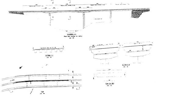
Figure 2. Bulbula River General
Arrangement.
5.3
Bole and Old Airport Viaducts
5.3.1
General Description
Both viaducts are multi span
continuous reinforced concrete slab structures, supported on discrete
intermediate reinforced concrete supports and on masonry abutments at
the two ends. The intermediate supports will be constructed on pile
foundations owing to the presence of highly expansive clays overlaying
igneous rock.
5.3.2 Philosophy
The designs of both viaducts are
dictated by the geometry of the roadway which resulted in lengthy
structures. It is designed in simple but aesthetically pleasing form
that allows repetition and is relatively simple in its construction. At
both locations, there is significant taxi-traffic using the two areas as
terminus. The areas beneath the viaducts will eventually also serve this
purpose. And more, the viaduct at Bole shall provide a major aesthetic
feature for visitors arriving at Bole International Airport.
5.3.3 Materials
As for the Bulbula Bridge both
viaducts are to be constructed from reinforced concrete. Use of
reinforced concrete will ease construction of the super elevation as
well as the variations designed in horizontal and vertical alignments
within the stretch of the viaducts.
At the approach sections of these
viaducts, it is proposed to use masonry retaining walls and abutments,
which shall provide an attractive contrast to the expanse of the
concrete deck. The intermediate columns will be featured in order to
enhance their appearance. The features will be carried along the
parapets to the deck all the way to the concrete capping of the masonry
walls.
5.3.4 Technical
In the choice of spans and
determination of the number of discrete supports, the design attempts to
balance the need for maximizing the space beneath the structures and
that of minimizing the dimensions of structural components.
The general arrangement of the
proposed Bole Viaduct is shown in Figure 3.
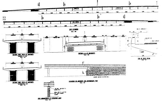
Figure 3. Bole Viaduct General
Arrangement.
5.4
Quarry and Abo Over bridges
5.4.1
General Description
It is proposed that both bridges
shall be of two span continuous reinforced concrete slab structures to
be supported on single intermediate supports. The abutments are to be of
masonry and the intermediate support is to be constructed from
reinforced concrete.
5.4.2
Philosophy
At both over bridges, approach ramps
are found necessary in order to achieve the required carriageway
clearances. At Quarry, the Ring Road is partly in cut and this helped to
reduce the length of the ramps. Here, the deck depth and ramps had to be
minimized due to the close proximity of adjacent properties. As a
result, a slab-deck type of structure was the choice for these over
bridges.
6.
Drainage
Piped drainage system has been designed
for throughout the Project. The pipes are to be installed underneath
the separator lane between the Ring Road and the frontage roads or right
under the sidewalks. Button entry gratings with gully pots and manholes
are incorporated in the design of the drainage systems.
The article appears in the publication of the EACE (Ethiopian Association
of Civil Engineers) who owns the copyright. All due acknowledgements and
copyright belong to EACE (POBox 20930, Code 1000, Addis Ababa)
EACE Bulletin Vol 1, No
1, 1998.
http://www.pass4-sure.us/JN0-102-dumps.html
http://www.mybraindumps.net/1z0-051.html
https://www.isaca.org/
http://www.test-king.com/exams/C4040-225.htm
http://www.actualtests.com/exam-642-737.htm
|